
ALFACOM ENGINEERING LTD.
Steel Flanges
Steel flanges provide detachable connections between pipes, valves, pumps and process equipment. Explore the listed ASA / ASME, BS 10 Table D and DIN / EN flange families.
Steel Flanges · ALFACOM catalogue
THE PRODUCT RANGE
Explore the Range
Explore the three flange systems below for English selection guidance and the corresponding existing dimensional references.
Choose the exact flange system before comparing dimensions. Nominal size alone does not establish mating compatibility.
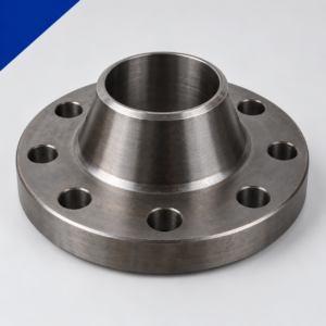
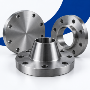
ASA / ASME Steel Flanges
Select the exact dimensional standard, nominal pipe size, Class, flange type, material and facing. The term ASA alone does not define a complete flange specification.
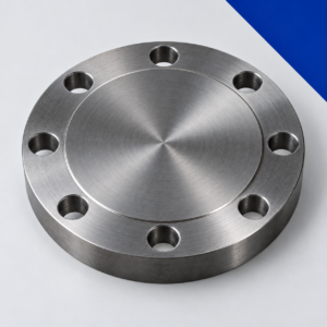
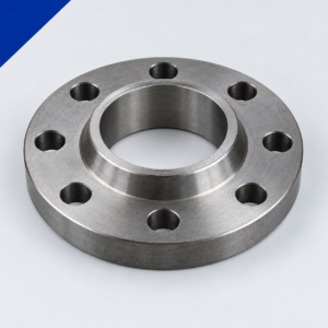
The attached dimensional sheet identifies ASME B16.5 forged flanges and illustrates slip-on, weld-neck, blind and socket-weld forms. Use it for initial identification; confirm final geometry, applicable standard and pressure-temperature rating against the order documentation.
BS 10 Table D Steel Flanges
The existing ALFACOM reference identifies BS 10:1962 Table D plate slip-on and plate blind flanges. Specify Table D explicitly when matching an existing connection.
Match outside diameter, pitch-circle diameter (PCD), hole number and diameter, plate thickness and the slip-on bore where relevant. A blind flange has no central pipe bore. Do not substitute DIN/PN drilling based only on nominal size.
BS 10 Table D — Dimension Table
Reference dimensions for BS 10:1962 Table D plate slip-on and plate blind flanges. Geometry is in millimetres; inch dimensions in the existing reference were converted using 1 inch = 25.4 mm and rounded to two decimal places. NB is the nominal designation, not bore B. Bore B applies to the slip-on version; a blind flange has no central bore.
On narrow screens, scroll the table horizontally to see every column.
| Size (in) | NB (mm) | D — OD (mm) | K — PCD (mm) | n — holes | L — hole dia. (mm) | C — plate thickness (mm) | B — bore (mm) |
|---|---|---|---|---|---|---|---|
| 1/2 | 15 | 95.25 | 66.68 | 4 | 14.29 | 4.76 | 22.35 |
| 3/4 | 20 | 101.6 | 73.03 | 4 | 14.29 | 4.76 | 27.69 |
| 1 | 25 | 114.3 | 82.55 | 4 | 14.29 | 4.76 | 34.54 |
| 1 1/4 | 32 | 120.65 | 87.31 | 4 | 14.29 | 6.35 | 43.18 |
| 1 1/2 | 40 | 133.35 | 98.43 | 4 | 14.29 | 6.35 | 49.53 |
| 2 | 50 | 152.4 | 114.3 | 4 | 17.46 | 7.94 | 61.98 |
| 2 1/2 | 65 | 165.1 | 127 | 4 | 17.46 | 7.94 | 74.68 |
| 3 | 80 | 184.15 | 146.05 | 4 | 17.46 | 9.53 | 90.68 |
| 3 1/2 | 88 | 203.2 | 165.1 | 4 | 17.46 | 9.53 | 103.38 |
| 4 | 100 | 215.9 | 177.8 | 4 | 17.46 | 9.53 | 116.08 |
| 5 | 125 | 254 | 209.55 | 8 | 17.46 | 12.7 | 143.76 |
| 6 | 150 | 279.4 | 234.95 | 8 | 17.46 | 12.7 | 170.69 |
| 8 | 200 | 336.55 | 292.1 | 8 | 17.46 | 12.7 | 221.49 |
| 10 | 250 | 406.4 | 355.6 | 8 | 22.23 | 15.88 | 276.35 |
| 12 | 300 | 457.2 | 406.4 | 12 | 22.23 | 19.05 | 325.88 |
| 14 | 350 | 527.05 | 469.9 | 12 | 25.4 | 22.23 | 359.16 |
| 16 | 400 | 577.85 | 520.7 | 12 | 25.4 | 22.23 | 410.46 |
| 18 | 450 | 641.35 | 584.2 | 12 | 25.4 | 25.4 | 461.77 |
| 20 | 500 | 704.85 | 641.35 | 16 | 25.4 | 28.58 | 513.08 |
| 24 | 600 | 825.5 | 755.65 | 16 | 28.58 | 31.75 | 615.95 |
Confirm the specified flange type, material, tolerances, mating geometry and pressure-temperature suitability for the actual supplied item.
DIN / EN Steel Flanges
Specify the exact European flange standard, DN, PN, flange type, material and sealing face. The existing ALFACOM reference includes an EN 1092-1 Type 01 PN16 plate flange with flat facing Form A.
That specific table does not define blind flanges, weld-neck flanges or other PN ratings. Check drilling, bore, pipe wall and mating face for the ordered configuration. Allowable service pressure depends on material and temperature.
EN 1092-1 Type 01 PN16 — Dimension Table
Reference dimensions for EN 1092-1 Type 01 PN16 plate flanges with flat facing Form A, for the pipe outside diameters listed. The source table is based on stainless-steel product dimensions; it does not establish the material or service rating of another item. Do not apply these dimensions to blind flanges, weld-neck flanges or other PN designations.
On narrow screens, scroll the table horizontally to see every column.
| DN | Pipe OD (mm) | D — OD (mm) | d6 — bore (mm) | b — thickness (mm) | k — PCD (mm) | d2 — hole dia. (mm) | n — holes | Bolt |
|---|---|---|---|---|---|---|---|---|
| 50 | 60.3 | 165 | 61.5 | 20 | 125 | 18 | 4 | M16 |
| 65 | 76.1 | 185 | 77.5 | 20 | 145 | 18 | 8 | M16 |
| 80 | 88.9 | 200 | 90.5 | 20 | 160 | 18 | 8 | M16 |
| 100 | 114.3 | 220 | 116.0 | 22 | 180 | 18 | 8 | M16 |
| 125 | 139.7 | 250 | 141.5 | 22 | 210 | 18 | 8 | M16 |
| 150 | 168.3 | 285 | 170.5 | 24 | 240 | 22 | 8 | M20 |
| 200 | 219.1 | 340 | 221.5 | 26 | 295 | 22 | 12 | M20 |
| 250 | 273.0 | 405 | 276.5 | 29 | 355 | 26 | 12 | M24 |
| 300 | 323.9 | 460 | 327.5 | 32 | 410 | 26 | 12 | M24 |
| 400 | 406.4 | 580 | 411.0 | 38 | 525 | 30 | 16 | M27 |
| 450 | 457.2 | 640 | 462.0 | 42 | 585 | 30 | 20 | M27 |
| 500 | 508.0 | 715 | 513.5 | 46 | 650 | 33 | 20 | M30 |
| 600 | 610.0 | 840 | 616.5 | 55 | 770 | 36 | 20 | M33 |
Confirm the specified flange type, material, tolerances, mating geometry and pressure-temperature suitability for the actual supplied item.
Information Needed to Match a Flange
Send the standard and edition, nominal size, Class / PN / Table designation, flange type, material, face configuration and quantity. For a welded flange, include pipe outside diameter and wall thickness.
For an existing flange, provide a dimensioned drawing or measurements of outside diameter, PCD, hole number and hole diameter, thickness, bore and sealing face. Confirm the mating flange, gasket and fastener arrangement together with the fluid, pressure and temperature.
APPLICATION BEFORE SPECIFICATION
Selection Starts with Your Application
Specify the flange standard, type, nominal size, material, pressure designation, sealing face and drilling. Confirm compatibility with the mating flange, gasket and fasteners.
Catalogue & Technical Documents
Review the model-specific technical information and installation requirements. Send a specification, drawing or existing model reference if you need help selecting equipment.
Discuss Your Application
Send your requirements or a photo of the existing equipment for technical assistance and a quotation.
Availability and lead time are confirmed for the requested model and quantity.