Z-Tide CHF Silent Check Valve
Full-open lift-type check valve for preventing reverse flow in pressurised water pipework, including pump discharge lines.

ALFACOM ENGINEERING LTD.
This family covers pressure regulation, air release, water hammer control, backflow prevention and flow control for water and infrastructure systems. Listed Z-Tide families include pressure reducing valves, air release valves, water hammer arresters, check valves, foot valves and control valves.
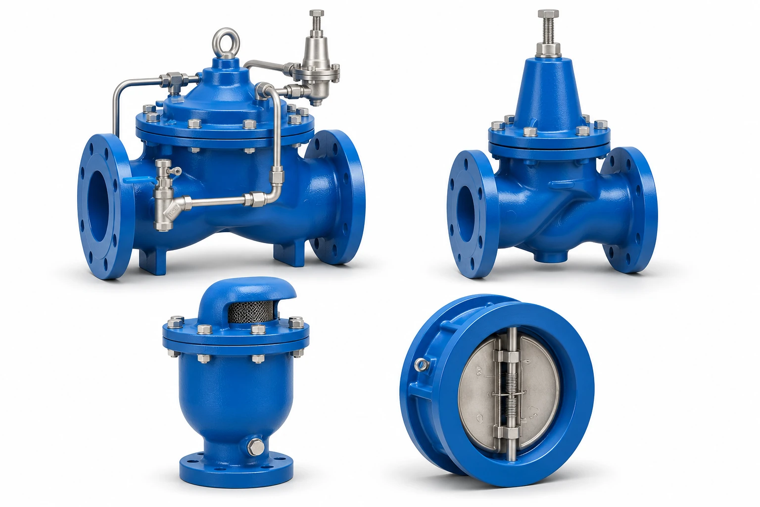
Water System Control Valves and Equipment · Illustrative image
Review the equipment functions and reference diagrams below. Each entry includes English guidance and an ALFACOM-hosted technical document.
Full-open lift-type check valve for preventing reverse flow in pressurised water pipework, including pump discharge lines.
Pilot-controlled valve family for automatic regulation of a water system. The main valve and its control circuit must be selected together for the required function.
An air chamber separated by a diaphragm absorbs hydraulic pressure surges caused by rapid changes in flow.
Direct-acting pressure reducing valves with a stainless steel 316 body. RET denotes the threaded version; REF denotes the flanged version.
Float-operated valves for releasing accumulated air from pressurised water pipelines.
A reference diagram showing how pressure regulation, strainers, check valves, air release and surge-control equipment may be arranged in a water system.
A reference diagram showing example valve and control arrangements for fire protection pipework.
A controlled valve arrangement intended to coordinate opening and closing with pump operation and reduce abrupt changes in pipeline flow.
Foot valves combine a non-return function with an inlet screen at the suction end of a pump line. The catalogue shows a cleaning lever, with FVT threaded and FVF flanged versions.
Full-open lift-type check valve for preventing reverse flow in pressurised water pipework, including pump discharge lines.
Select for the required flow and pressure loss, installation direction, body material and connections. Confirm the closing behaviour against the pump and system conditions.
Pilot-controlled valve family for automatic regulation of a water system. The main valve and its control circuit must be selected together for the required function.
Specify the control duty, inlet and outlet pressures, flow range, power or control signals where applicable, and the required fail response. The catalogue covers several control arrangements; they are not interchangeable.
An air chamber separated by a diaphragm absorbs hydraulic pressure surges caused by rapid changes in flow.
Sizing requires the pipe length and diameter, flow velocity, valve closing time or pump stopping behaviour, and allowable surge pressure. Select the vessel arrangement and installation location for the actual system.
Direct-acting pressure reducing valves with a stainless steel 316 body. RET denotes the threaded version; REF denotes the flanged version.
Specify minimum and maximum inlet pressure, required outlet pressure at operating flow, fluid, temperature and connections. The linked catalogue also includes titanium, low-pressure and micro-pressure versions; use the RET / REF stainless steel section for this family.
Float-operated valves for releasing accumulated air from pressurised water pipelines.
The catalogue specifies vertical installation and recommends high points in the pipeline. Confirm the required venting duty, body and seal materials, operating pressure and temperature; an air-release valve is not automatically a vacuum-admission valve.
A reference diagram showing how pressure regulation, strainers, check valves, air release and surge-control equipment may be arranged in a water system.
Use this illustration to discuss system functions and equipment locations. Project-specific hydraulic design, sizing and installation details must be determined for the actual site.
A reference diagram showing example valve and control arrangements for fire protection pipework.
The diagram is a discussion aid. It does not establish approval or compliance for any individual valve or completed fire protection system; confirm the project requirements and required documentation separately.
A controlled valve arrangement intended to coordinate opening and closing with pump operation and reduce abrupt changes in pipeline flow.
Specify the pump operating sequence, flow range, pressure conditions, control supply and required interlocks. Review the model-specific control circuit and installation instructions before selecting the arrangement.
Foot valves combine a non-return function with an inlet screen at the suction end of a pump line. The catalogue shows a cleaning lever, with FVT threaded and FVF flanged versions.
Confirm the suction conditions, screened inlet area, connections and material. The linked catalogue specifies vertical installation; allow access for cleaning and maintenance.
APPLICATION BEFORE SPECIFICATION
Provide inlet and outlet pressures, flow rate, size, connections, materials and operating conditions. ALFACOM assists with selecting a suitable model for the application.
Review the model-specific technical information and installation requirements. Send a specification, drawing or existing model reference if you need help selecting equipment.
Send your requirements or a photo of the existing equipment for technical assistance and a quotation.
Availability and lead time are confirmed for the requested model and quantity.