
ALFACOM ENGINEERING LTD.
Steam Pipeline Ancillaries
Pipeline ancillaries support drainage, air removal, filtration, flow observation and reverse-flow or vacuum prevention in suitable applications. Select each component for its specific function and service conditions.
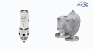
Steam Pipeline Ancillaries · Illustrative catalogue image
THE PRODUCT RANGE
Explore the Range
Browse All Models & Technical Documents →
Explore the equipment and selection topics below, then review the detailed catalogue for the selected product.
Explore the model guidance and selection notes in English. Technical document buttons below open model-specific PDFs hosted on this website.
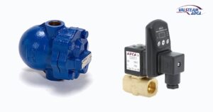
Compressed Air Condensate Drainers
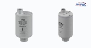
Air Vents
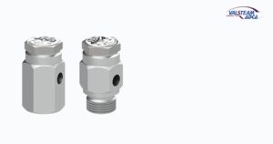
Vacuum Breakers
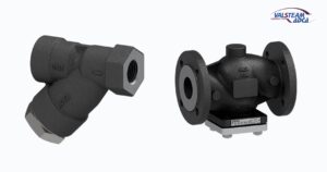
Pipeline Strainers
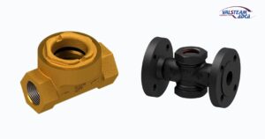
Sight Glasses
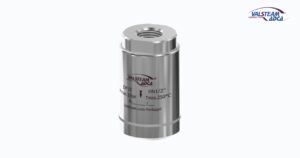
Steam Silencers
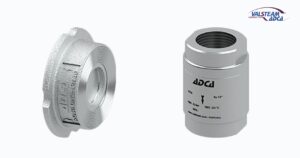
Check Valves
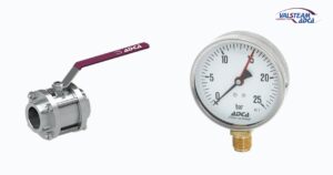
Valves and Cocks
Model & Technical Document Index
Select the equipment family and model below. Review the application and model-specific document before requesting selection and a quotation.
Float Drainers for Air & Gas
Compressed-Air Condensate Drainers
Automatic Air & Gas Vents for Liquids
Vacuum Breakers
Pipeline Strainers
Sight Glasses & Sight Checkers
Steam & Air Discharge Diffusers
Isolation Valves, Gauge Connections & Level Indication
Equipment Details & Selection
Float Drainers for Air & Gas
FA21.1 · Air & Gas Float Trap
Automatic float-operated condensate trap for compressed-air or compatible gas systems, including aftercoolers, separators and distribution lines.
Select the FA21.1 body and discharge mechanism using condensate load, differential pressure, fluid density and material compatibility. Verify the installation and any required balance connection in its model document.
FA31.1 · Air & Gas Float Trap
Automatic float-operated condensate trap for compressed-air or compatible gas systems, including aftercoolers, separators and distribution lines.
Select the FA31.1 body and discharge mechanism using condensate load, differential pressure, fluid density and material compatibility. Verify the installation and any required balance connection in its model document.
FA41.1 · Air & Gas Float Trap
Automatic float-operated condensate trap for compressed-air or compatible gas systems, including aftercoolers, separators and distribution lines.
Select the FA41.1 body and discharge mechanism using condensate load, differential pressure, fluid density and material compatibility. Verify the installation and any required balance connection in its model document.
FA25.1 · Air & Gas Float Trap
Automatic float-operated condensate trap for compressed-air or compatible gas systems, including aftercoolers, separators and distribution lines.
Select the FA25.1 body and discharge mechanism using condensate load, differential pressure, fluid density and material compatibility. Verify the installation and any required balance connection in its model document.
FA35.1 · Air & Gas Float Trap
Automatic float-operated condensate trap for compressed-air or compatible gas systems, including aftercoolers, separators and distribution lines.
Select the FA35.1 body and discharge mechanism using condensate load, differential pressure, fluid density and material compatibility. Verify the installation and any required balance connection in its model document.
FA45.1 · Air & Gas Float Trap
Automatic float-operated condensate trap for compressed-air or compatible gas systems, including aftercoolers, separators and distribution lines.
Select the FA45.1 body and discharge mechanism using condensate load, differential pressure, fluid density and material compatibility. Verify the installation and any required balance connection in its model document.
FA25.3 · Air & Gas Float Trap
Automatic float-operated condensate trap for compressed-air or compatible gas systems, including aftercoolers, separators and distribution lines.
Select the FA25.3 body and discharge mechanism using condensate load, differential pressure, fluid density and material compatibility. Verify the installation and any required balance connection in its model document.
FA35.3 · Air & Gas Float Trap
Automatic float-operated condensate trap for compressed-air or compatible gas systems, including aftercoolers, separators and distribution lines.
Select the FA35.3 body and discharge mechanism using condensate load, differential pressure, fluid density and material compatibility. Verify the installation and any required balance connection in its model document.
FA45.3 · Air & Gas Float Trap
Automatic float-operated condensate trap for compressed-air or compatible gas systems, including aftercoolers, separators and distribution lines.
Select the FA45.3 body and discharge mechanism using condensate load, differential pressure, fluid density and material compatibility. Verify the installation and any required balance connection in its model document.
Compressed-Air Condensate Drainers
FA17/G · DN15–20
Compact automatic float trap for draining condensate from compressed-air lines, separators and aftercoolers.
Use the small-body document for the selected size and connection. Confirm condensate load, differential pressure and installation arrangement.
FA17/G · DN40–50
Larger automatic float-trap family for compressed-air condensate drainage.
Use the DN40–50 dimensions and capacity data. Confirm the selected connection and operating differential pressure rather than extrapolating from the smaller FA17/G body.
FA20 · Compressed-Air Float Trap
Float-operated condensate trap for compressed-air and compatible gas lines.
The source requires an air-balance pipe to release trapped gas and allow condensate to enter. Include the balance connection, load and differential pressure in the installation design.
FA32 · Compressed-Air Float Trap
Float-operated trap for removing condensate from compressed-air and compatible gas systems.
An air-balance pipe is required by the source. Check the condensate load, differential pressure and complete inlet, outlet and balance-line arrangement.
FA16SS · Compressed-Air Float Trap
Compact stainless steel automatic float trap for compressed-air condensate drainage.
The source covers female threaded connections. Verify the selected connection, operating conditions and condensate capacity for the intended aftercooler, separator or line duty.
FA21SS · Compressed-Air Float Trap
Float-operated condensate trap for compressed-air and compatible gas systems.
The source requires an air-balance pipe. Confirm body construction, connection, differential pressure and condensate load for the complete installation.
CAD · Timed Compressed-Air Drain
Automatic drain combining an adjustable timer and solenoid valve for condensate collection points in compressed-air systems.
Set discharge duration and interval to suit the actual accumulation duty. Confirm electrical supply, pressure, connection and the receiving drain arrangement.
Automatic Air & Gas Vents for Liquids
AE16 · Automatic Air Eliminator
Float-operated air eliminator for water and compatible liquid systems, including HVAC applications.
This component removes gas from a liquid system. Confirm fluid density, compatibility, operating conditions and the vent-discharge arrangement.
AE16SS · Stainless Steel Air Eliminator
Stainless steel float-operated air eliminator for HVAC and compatible liquid systems.
Confirm the liquid density and material compatibility, as well as vent capacity and operating conditions. Route the air discharge appropriately for the actual fluid.
AE17G · Automatic Air Eliminator
Automatic float-operated air eliminator for water and compatible liquid systems.
Use the model-specific construction, liquid-density requirement and operating limits. Confirm installation at the appropriate air-collection point.
AE20 · Automatic Air Eliminator
Carbon steel air eliminator for cold, hot or superheated water and other compatible liquids within the source limits.
Select for the actual pressure, temperature and liquid density. Confirm the threaded or flanged configuration and safe vent routing.
AE30SS · Sealed Air Eliminator
Sealed stainless steel float-type air eliminator for hot-water and compatible liquid systems.
Check liquid density, operating limits and the permitted installation arrangement. The component removes air from liquid; it is not a compressed-air condensate trap.
AE32 · Automatic Air Eliminator
Carbon steel float-operated air eliminator for hot-water and compatible liquid systems.
Confirm the liquid-density requirement, venting duty and selected threaded or flanged connection. Verify operating pressure and temperature together.
AE35.2 · Automatic Air / Gas Vent
Carbon steel automatic float vent for removing air or gas from water and compatible liquid systems.
The source describes start-up venting and continuous modulating discharge through a single orifice. Select using the venting load, pressure and liquid properties.
AE45.2 · Automatic Air / Gas Vent
Stainless steel automatic float vent for removing air or gas from water and compatible liquid systems.
Confirm start-up and normal venting loads, fluid density, pressure and compatibility. Use the AE45.2-specific connection and installation data.
Vacuum Breakers
VB16 · Vacuum Breaker
Automatic vacuum breaker for relieving unwanted vacuum in steam-heated equipment.
The source lists male threaded connections. Confirm the installation point and connection for the heat exchanger, coil, vessel or other equipment duty.
VB21 / VB21M · Vacuum Breaker
Automatic vacuum-breaking equipment for steam-heated vessels, coils and heat exchangers.
The source lists female threaded connections. Confirm the exact VB21 or VB21M construction and installation requirement for the selected arrangement.
Pipeline Strainers
IS140 · Y Strainer
Pipeline strainer for retaining dirt and impurities ahead of compatible traps, valves and other equipment.
Check the threaded connection, screen specification, fluid compatibility and operating limits. Allow access for inspection and cleaning.
IS16F · Flanged Y Strainer
Cast iron flanged Y-strainer family for protecting compatible pipeline equipment from debris.
Specify fluid, flow, pressure and temperature together with the screen requirement. Confirm installation orientation and maintenance access.
IS116 · Y Strainer
Forged steel Y-strainer family for protecting compatible traps, regulators and pipeline equipment.
Confirm the selected threaded or flanged version and screen. Check pressure drop and provide cleaning access in the installation.
IS40T · EN-Flanged T Strainer
Cast steel T-strainer family for compatible steam, water, oil and air pipeline duties.
Use the EN-flanged model document for connection and dimensional data. Select the screen and confirm allowable pressure drop and cleaning access.
IS40T · ASME-Flanged T Strainer
T-strainer family for protecting compatible pipeline equipment from dirt and debris.
Use the ASME-family document for the actual flange class and dimensions. Confirm screen specification, operating conditions and maintenance access.
Sight Glasses & Sight Checkers
SCK · Sight Glass & Check Valve
Combined visual flow-indication and non-return equipment.
Confirm flow direction, permitted orientation, fluid and operating conditions. A visible flow indication does not by itself measure condensate flow rate.
SW12 · Single-Window Sight Glass
Single-window sight-glass equipment for visual inspection of compatible pipeline flow.
Confirm the selected connection, orientation and pressure-temperature limits, including the glass and seals. Allow access for inspection and maintenance.
DW40S · Double-Window Sight Glass
Double-window sight-glass family for visual observation of compatible pipeline service.
Use the DW40S construction and dimensional data. Verify the pressure-temperature limits and glass/seal compatibility for the selected duty.
DW40SS · Double-Window Sight Glass
Double-window sight-glass family for visual pipeline inspection.
Use the DW40SS-specific body, glass and seal data. Confirm the actual fluid and operating conditions before selection.
DW12 · Bronze Double-Window Sight Glass
Bronze double-window sight glass for visual inspection of compatible line service.
Check glass, seal and body compatibility as a complete assembly. Confirm connection, orientation and operating conditions.
DW12G-SS · Double-Window Sight Glass
Double-window sight-glass family for observing compatible pipeline flow.
Confirm the exact G or SS construction and the applicable glass and seal limits. Use the model document for dimensions and installation.
Steam & Air Discharge Diffusers
DF15 · Steam & Air Diffuser
Discharge diffuser for suitable steam or air venting applications.
Provide discharge pressure, flow and the intended destination. Confirm the permitted installation arrangement; no quantified noise reduction is assumed.
Check Valves
RT25 · Check Valve
Non-return valve for compatible pipeline duties.
Confirm permitted flow direction and orientation, required opening conditions and the selected connection. Verify the actual fluid and operating envelope.
RD40 · Check Valve · DN15–100
Check-valve family for restricting reverse flow in compatible pipeline service.
Use the DN15–100 model document for installation, opening conditions and dimensions. Confirm the connection and actual operating duty.
RD40 · Check Valve · DN125–200
Larger RD40 check-valve family for compatible pipeline service.
Use the DN125–200 dimensional and installation data. Confirm flow direction, allowed orientation and the conditions needed for reliable closure.
Isolation Valves, Gauge Connections & Level Indication
GV32B · Bronze Globe Stop Valve
Bronze in-line stop valve for compatible steam, water, oil or air service.
Confirm the required isolation duty, connection and seat/seal compatibility. Verify the pressure-temperature limits for the actual operating conditions.
M3S1 · Three-Piece Ball Valve
Three-piece ball-valve family for compatible isolation duties.
Confirm the exact construction, bore and end connections in the model document. Select seats and seals for the fluid and operating conditions. The source specifies isolation use, fully open or fully closed, rather than modulating control.
M3i5 · Reduced-Bore Ball Valve
Reduced-bore three-piece ball-valve family for compatible pipeline isolation.
Consider the reduced flow passage when checking pressure drop and required flow. Confirm seat, seal and connection details. The source specifies isolation use, fully open or fully closed, rather than modulating control.
M3i1 · Full-Bore Ball Valve
Full-bore three-piece ball-valve family for compatible pipeline isolation.
Confirm the actual end connection and bore for the selected size. Verify seat and seal suitability and the model-specific operating limits. The source specifies isolation use, fully open or fully closed, rather than modulating control.
MWS1 / MWi1 · Wafer Ball Valve
Wafer ball-valve families for compatible pipeline isolation.
Specify the required construction and mating flanges explicitly. Check face-to-face dimensions, seats, seals and the pressure-temperature limits. The source specifies isolation use, fully open or fully closed, rather than modulating control.
NV400 · Needle Stop Valve
Needle stop valve for isolating steam and other compatible industrial fluids.
Select for the specified isolation duty and connection. Verify construction and operating limits; a needle-shaped closure does not by itself establish a modulating-control duty.
MAN-100 · Pressure Gauge
Pressure-gauge family for local pressure indication in compatible applications.
Specify pressure range, connection position and thread, fluid and temperature. Confirm whether a siphon or isolation valve is needed for the installation.
GSC / GSU · Pressure-Gauge Siphons
Siphon accessories for suitable pressure-gauge installations on hot process service.
Select the required geometry and connections. Verify material compatibility and the permitted pressure-temperature conditions for the complete gauge connection.
GSV · Pressure-Gauge Siphon
Siphon accessory for an appropriate hot-service pressure-gauge installation.
Confirm the GSV layout, connections and material. Specify the process conditions and the gauge arrangement together.
LGC135I · Level-Gauge Valves
Level-gauge valve arrangement for observing liquid level in compatible condensate pumps, reservoirs and other equipment.
The source allows supply with or without glass. Confirm the complete glass-and-valve scope, indication length, connections and operating conditions.
APPLICATION BEFORE SPECIFICATION
Selection Starts with Your Application
Define the required function, fluid, pressure and temperature, connections, flow direction and maintenance access. Review installation orientation and the selected model documentation.
Catalogue & Technical Documents
Review the model-specific technical information and installation requirements. Send a specification, drawing or existing model reference if you need help selecting equipment.
Discuss Your Application
Send your requirements or a photo of the existing equipment for technical assistance and a quotation.
Availability and lead time are confirmed for the requested model and quantity.